Second tuto with BlinkGpioExample but we are using an FMU configured only for this project.
Some examples are distributed with Pi4J jar.
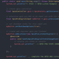
One of the simplest is BlinkGpioExample : led1 blinks every 1/2 seconds during 15 seconds and led2 blinks every second but speed up the rate when button is pressed.
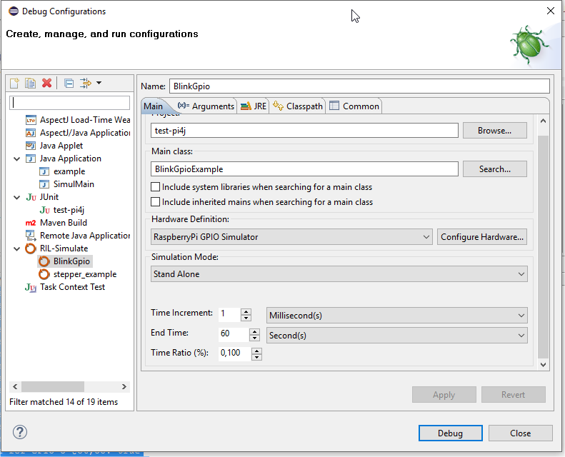
Eclipse Debug Configuration
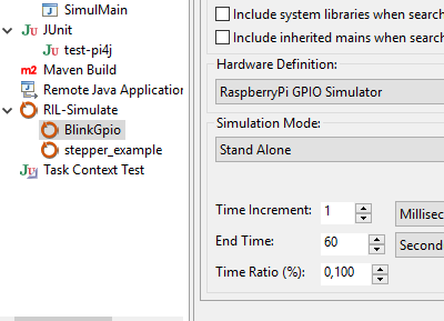
After installing (see getting started) and creating your project in eclipse, you have to set up your debug configuration:
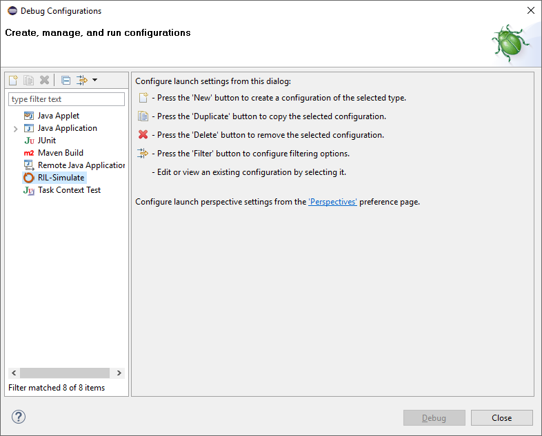
Then Right click on RIL-Simulate and choose new configuration
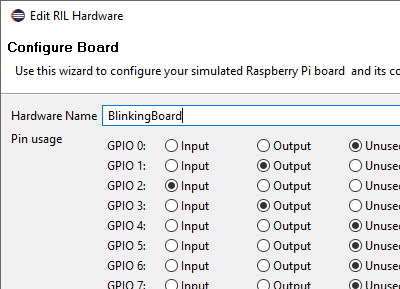
Board configuration
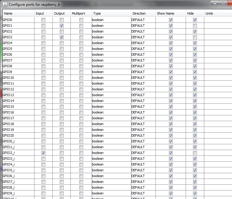
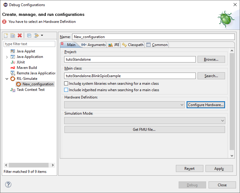
You now need to choose which hardware you want to use.
Even with a single Raspberry Pi board, there is a lot of different configurations.
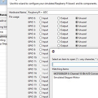
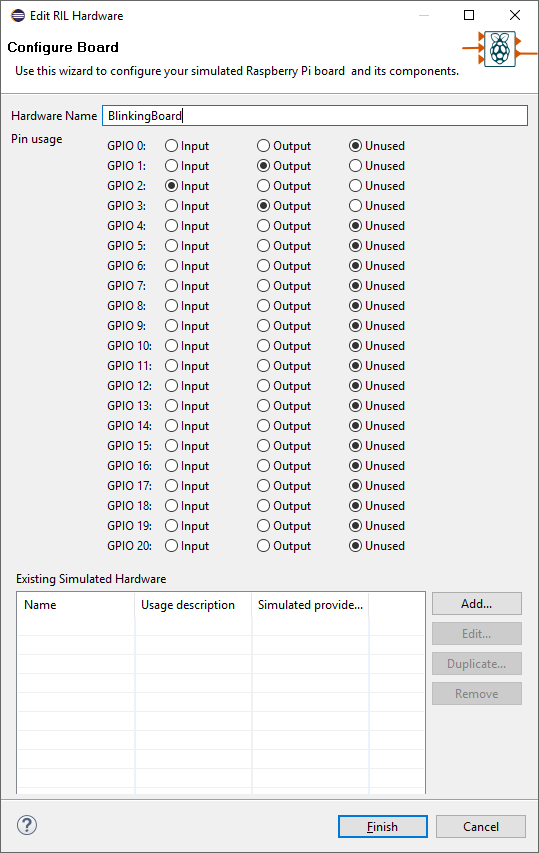
In this example, GPIO1 and GPIO3 are used as outputs and GPIO2 is an input.
So, click on “Configure Board”, in the “Manage Hardware list” click on “Add…”
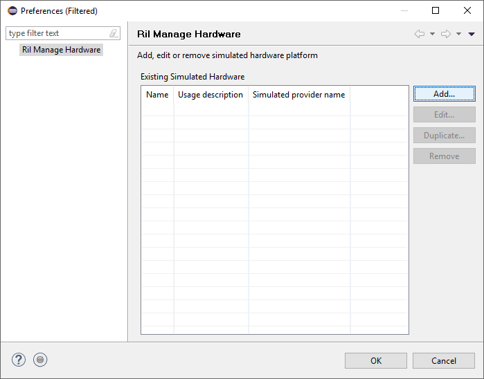
Name your new hardware, check GPIO 1 and 3 as outputs, 2 as input and leave the other unused and save it.
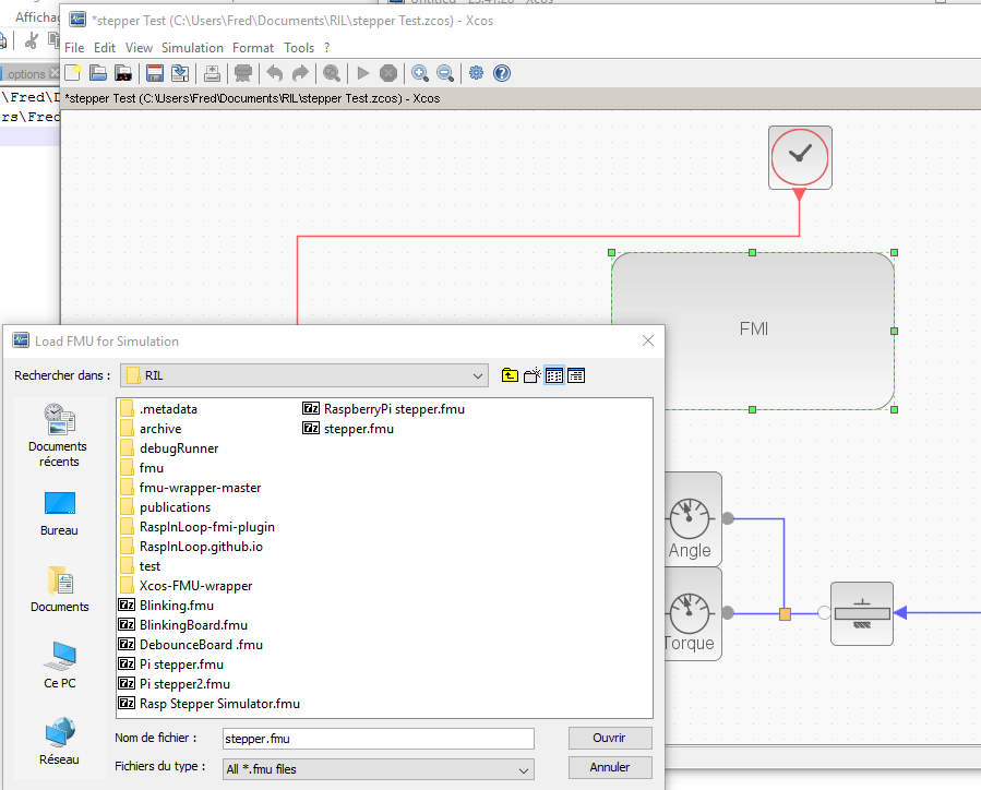
export fmu
Choosing “Functional Mockup Unit” as Simulation Mode allows you to get the FMU file. Click on the button and choose the location where the file will be saved.
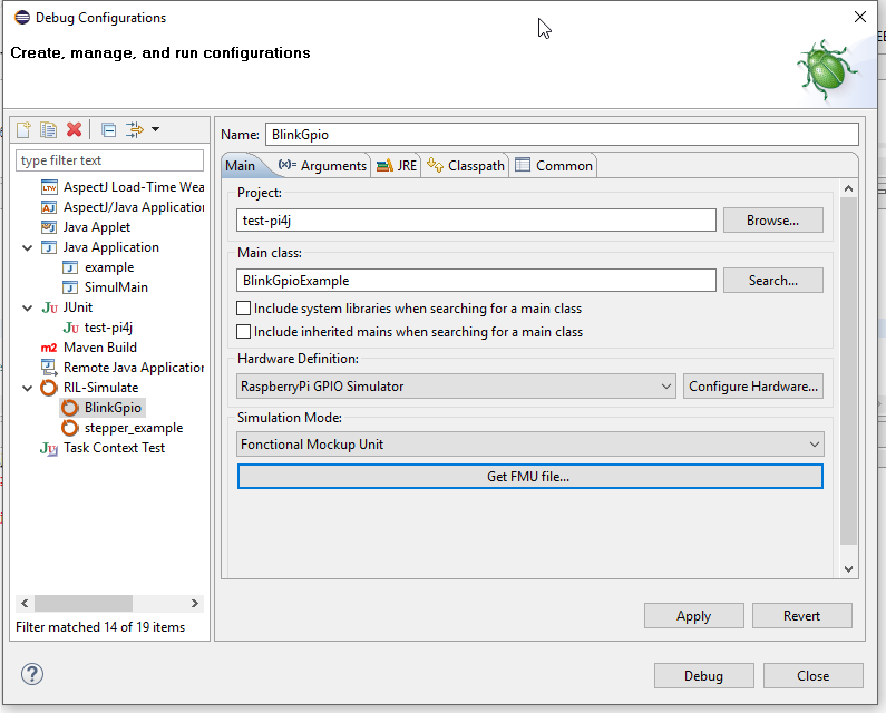
I have chosen : C:\Users\Fred\workspace\RIL-Tuto\RaspberryPi GPIO Simulator.fmu
Ptolemy Project
We will use Ptolemy II (The Ptolemy Projecy) as Computed Simulation Environment. This was the first (and currently the only one) tool I have tested with FMU co-simulation. Meanwhile, the FMI standard publish a compatibility table showing which tool is able to use FMU in master co-simulation.
Download and install Ptolemy II
Then Download the sample Ptolemy Project : www.raspinloop.org/data/Ptolemy_blinkGpioExample.xml and open it in Ptolemy:

file -> Open File and select the previously downloaded Ptolemy_blinkGpioExample.xml

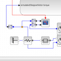
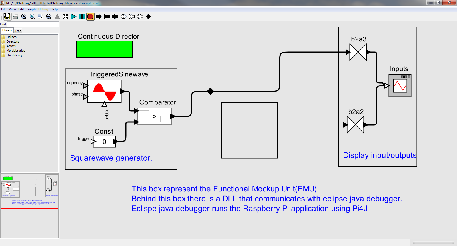
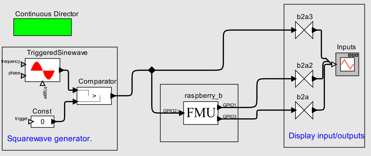
The project consists of 4 different parts:
- The Director
- Input signal generation
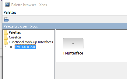
- The FMU binding
- Output Visualization
The Director
Ptolemy II is based on a class of models called actor-oriented models , or more simply, actor models.
Actors are components that execute concurrently and share data with each other by sending messages via ports.
The director is responsible to coordinate dataflow through port of each block. Continuous director is able to compute in each iteration, a fixed point for all signal values. In each iteration, time is advanced by an amount determined by the solver. (see Ptolemy getting started)
Our configuration for the Step size is :
stopTime : 30 The simulation stops after 30 seconds
initStepSize : 0.005
maxStepSize : 0.005
So, each iteration will represent 0.005 seconds. An interresting parameter could be synchronize to realtime. With this option each iteration will occurs evrey 0.005 second instead of ‘as soon as possible’.
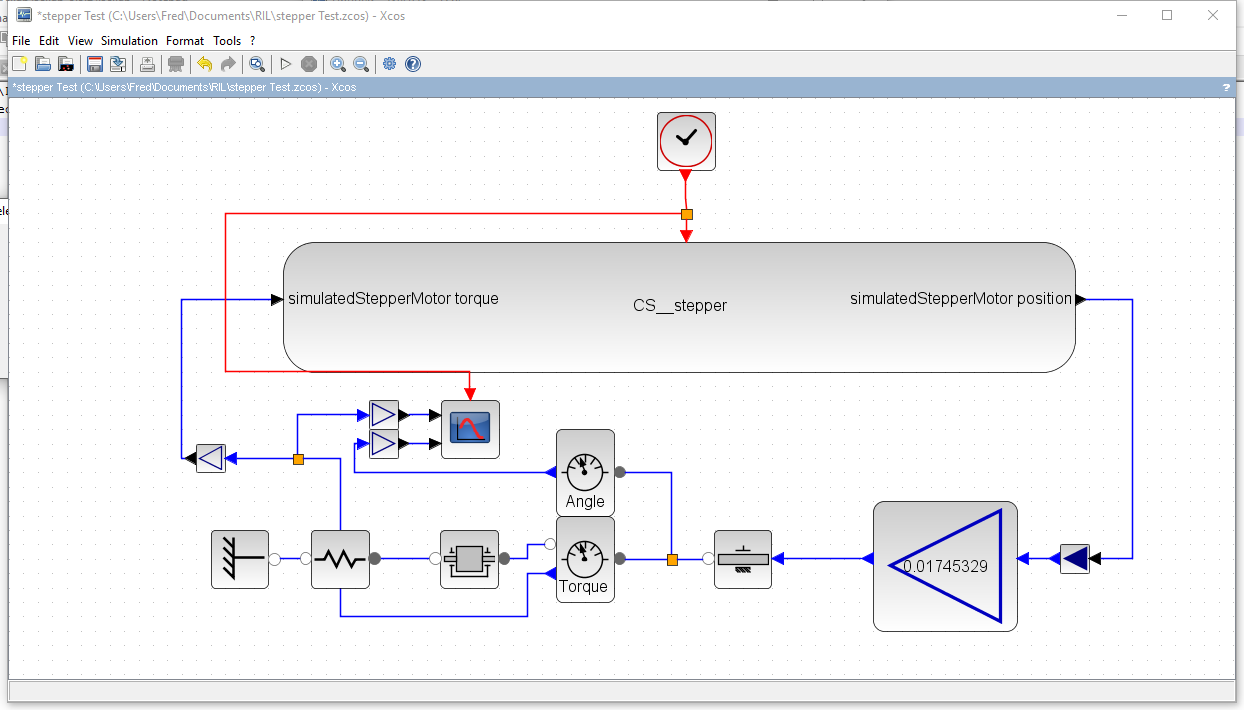
On the left part of the schema, we put a Squarewave generator to simulate the button signal. This was done with a sinewave generator and a comparator to set a signal to true when sinus is positive and false otherwise.
TriggeredSinewave is configured like this:
frequency : 0.1 0.1 Hertz means positive for 5 seconds positive and negative for the other 5 seconds…
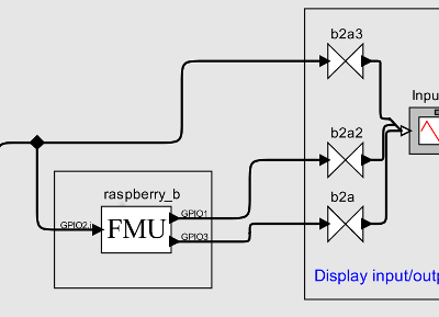
The FMU binding
This is the Main block. This block is the FMU (functional mockup unit) of Raspberry Pi. It will behave like all other blocks, with their inputs and output. Excepting of, this block will communicate with Eclipse to allow the java application to read inputs and set outputs.
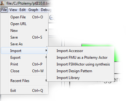
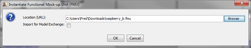
To configure it, we have to import FMU file it in Ptolemy:
.png)
DO NOT CHECK : Import for model exchange
We may ‘wire’ GPIO2_i to the wire outgoing from Squarewave generator.
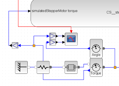
Output Visualization
In order to view the output, we use a block called timePlotter. This block doesn’t accept boolean as input, so we have to add a BooleanToAnything converter between FMU output and the plotter.
Now you may ‘wire’ your output to the converters
Note: You have to add another conveter to be able to wire the GPIO3. (try crtl-c -> ctrl-v)
You should have something like that….
RUN !
Now , we have to start your project in eclipse debugger (see install), wait for the message INFO [Server] Starting the simple server... and Run the model in ptolemy.
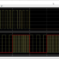
I hope you ‘ll feel the same exaltation as me seeing this graph.
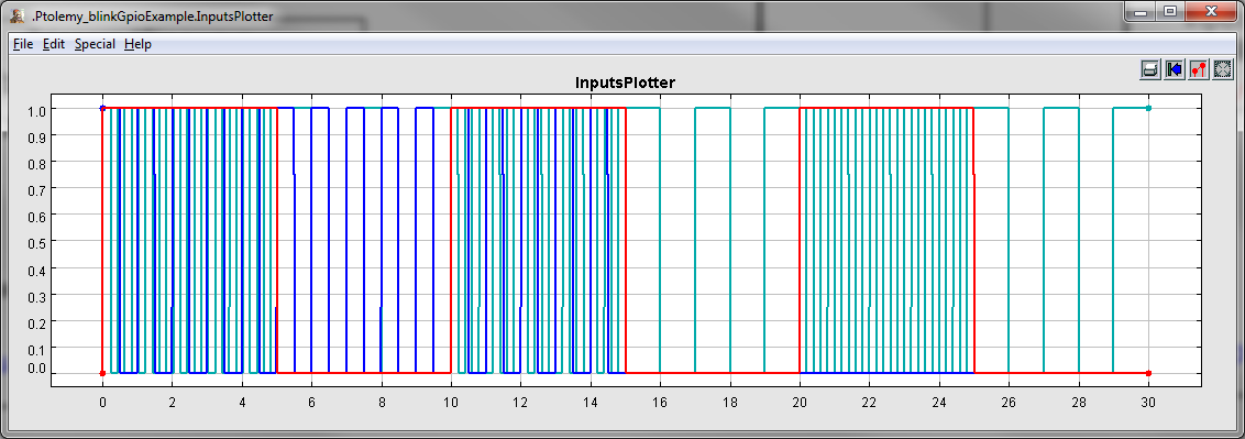
Pens:
- red: the input to GPIO02
- blue: the GPIO1 output (led1 // continuously blink the led every 1/2 second for 15 seconds)
- cyan: the GPIO3 output (led2 // continuously blink the led every 1 second except when button is pressed -> speed up the blink rate)